Multi Tone Generator Ic
Multi Tone Generator Circuit Multi Tone Generator Circuit
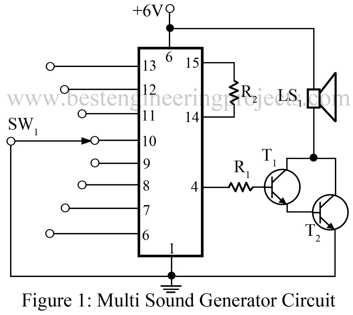
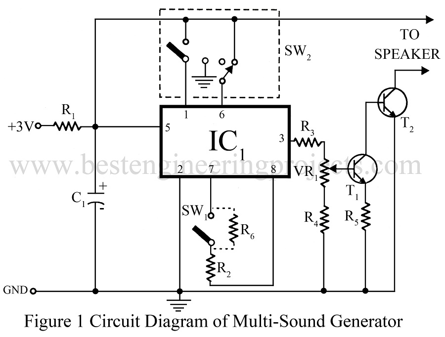
Multi Sound Generator Circuit Engineering Projects

Multi Sound Generator Electronics Project

Multi Tone Generator Circuit Diagram
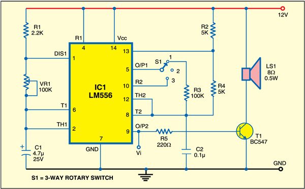
Triple Mode Tone Generator Detailed Circuit Diagram Available
Multitone Generator Circuit
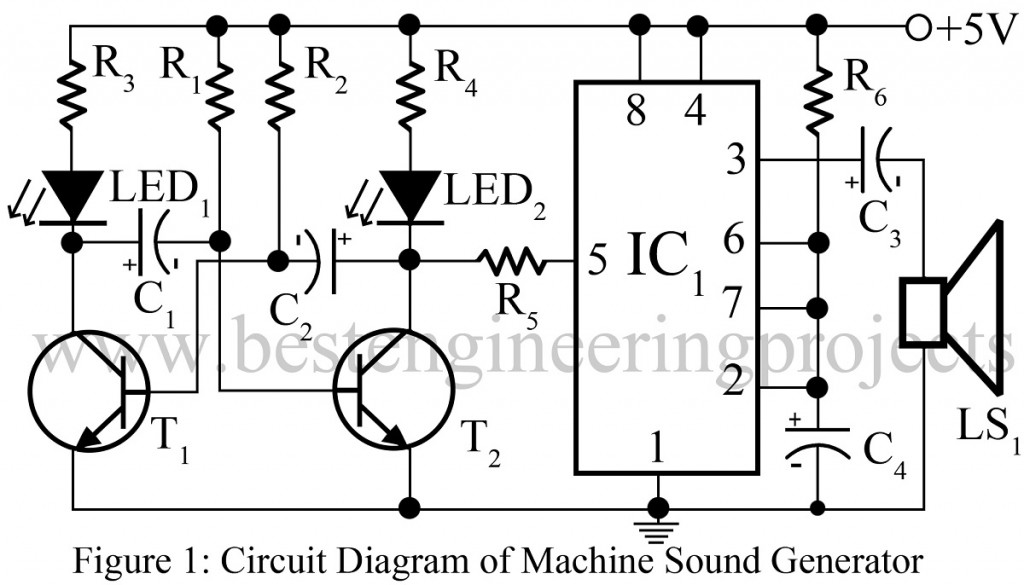
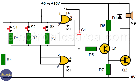
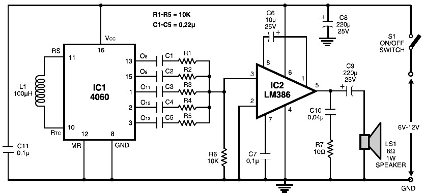
The voltage shift on pin 5 causes the frequency of the second oscillator to rise and fall.
Multi tone generator ic.
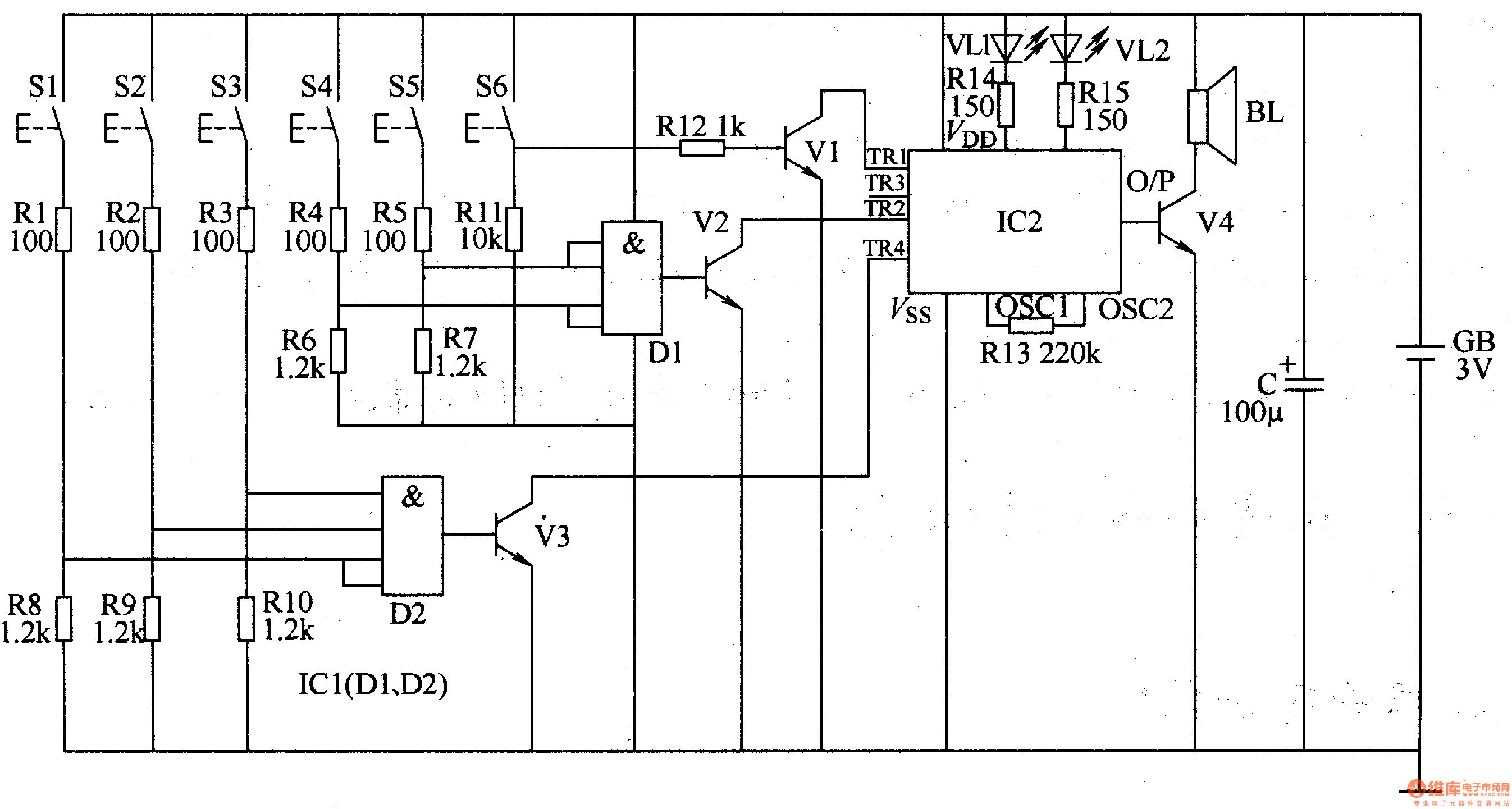
Multitone Siren Detailed Circuit Diagram Available
Multi Melody Generator With Instrumental Effect Circuit Diagram

Multitone Generator Door Bell Circuit Diagram Electronics Circuit Circuit Dc Circuit
Tone Generator Using Two 555 Timers Electronics Area
Multitone Generator Circuit Open Door Indicator Using Cd4001 Electronics Area
Tone Generator Circuit Simple Calling Bell Circuit
Multitone Siren Circuit Diagram And Instructions
Um3561 Sound Effect Generator Circuits Electronics Projects Circuits
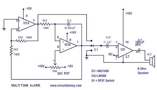
Simple Multi Tone Alarm Circuit With Diagram Op Amp

My Circuits 9 Simple Multitone Siren Circuit Circuit Siren Book Worth Reading
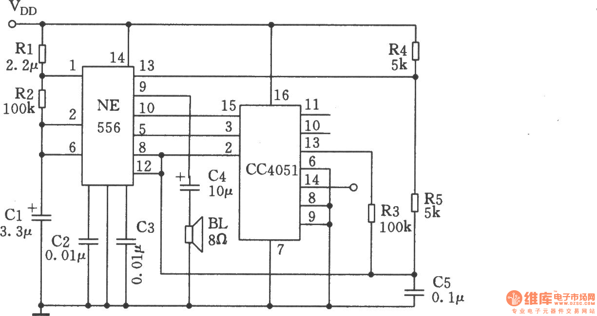
Multi Functional Sound Generator Composed Of Ne555 Cc4051 Noise Generator Signal Processing Circuit Diagram Seekic Com
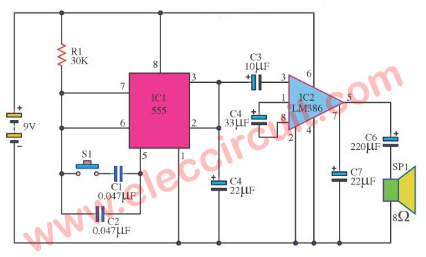
5 Circuits Of 555 Alarm Sound And Tone Generator Eleccircuit Com

Op Amp Tone Generator Circuit Analog Circuits Circuit Generation

Multi Tone Generator Bell Electronics Circuit Generation Circuit
Three Tone Electronic Doorbell 2 Electrical Equipment Circuit Circuit Diagram Seekic Com
Multitone Siren Alarm Electronic Schematic Diagram
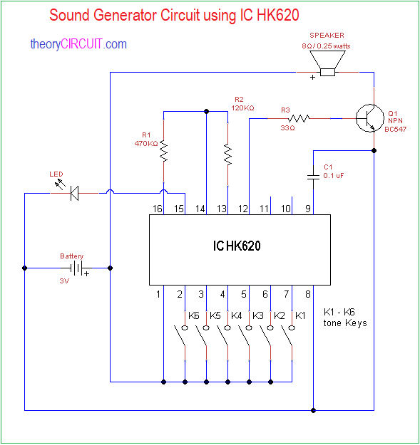
Sound Generator Circuit Using Ic Hk620

What Is Tone Generator Latest Application To Develop Melody And Siren Electrical Projects Circuit Electronics Projects
3

Electronic Projects Circuits Ic 555 Page 1 Chan 15290835 Rssing Com
Alarm Sound Generator Page 3 Of 4 Engineering Projects

Learn Melody Tone Generator Circuits Using Ht82207 Um3491 Mm5837 Eleccircuit Com Sound Effects Audio Amplifiers Generation
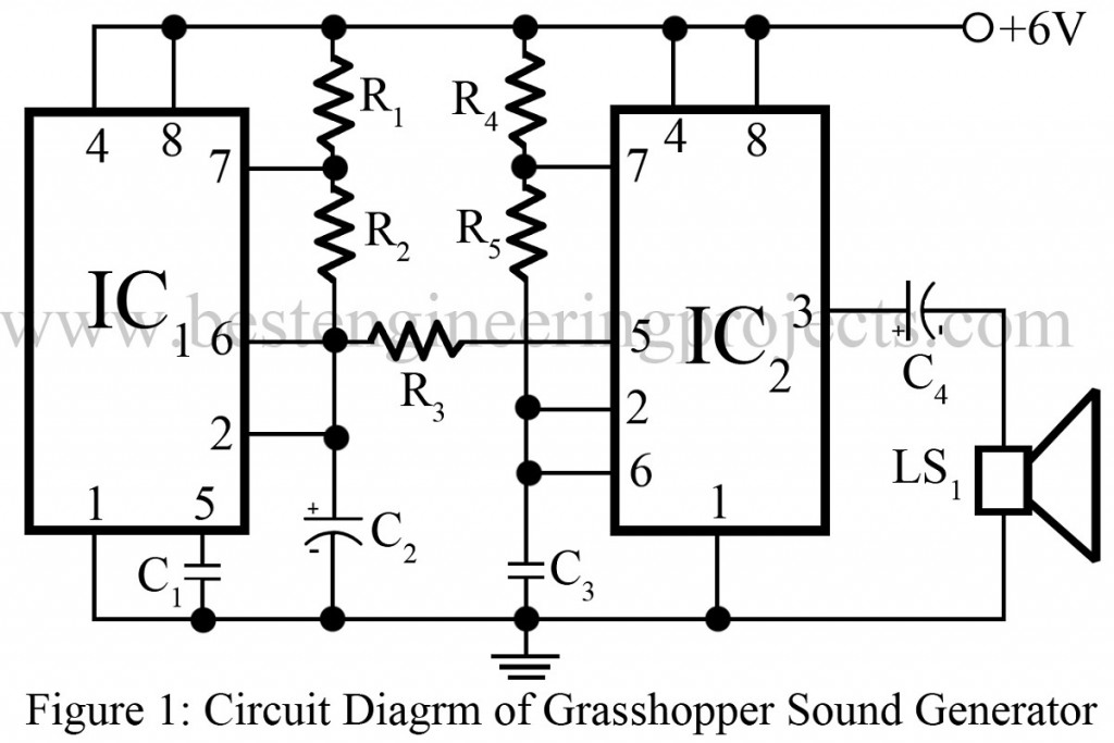
Grasshopper Sound Generator Circuit Using 555 Timer Ic

Learn Melody Tone Generator Circuits Using Ht82207 Um3491 Mm5837 Eleccircuit Com Music Tones Electronics Circuit Electronics Projects
Source : pinterest.com
